Isolation Signal Integrity and EMI Performance in Automotive Battery Systems
A battery-management system must collect accurate data from multiple monitoring modules across a high-voltage battery pack. Daisy-chain communication can reduce wiring complexity and support scalable pack architectures, but communication reliability must be designed into the complete signal path, not assumed from an individual module or component.
Why BMS Daisy Chains Need More Than a Simple Connection
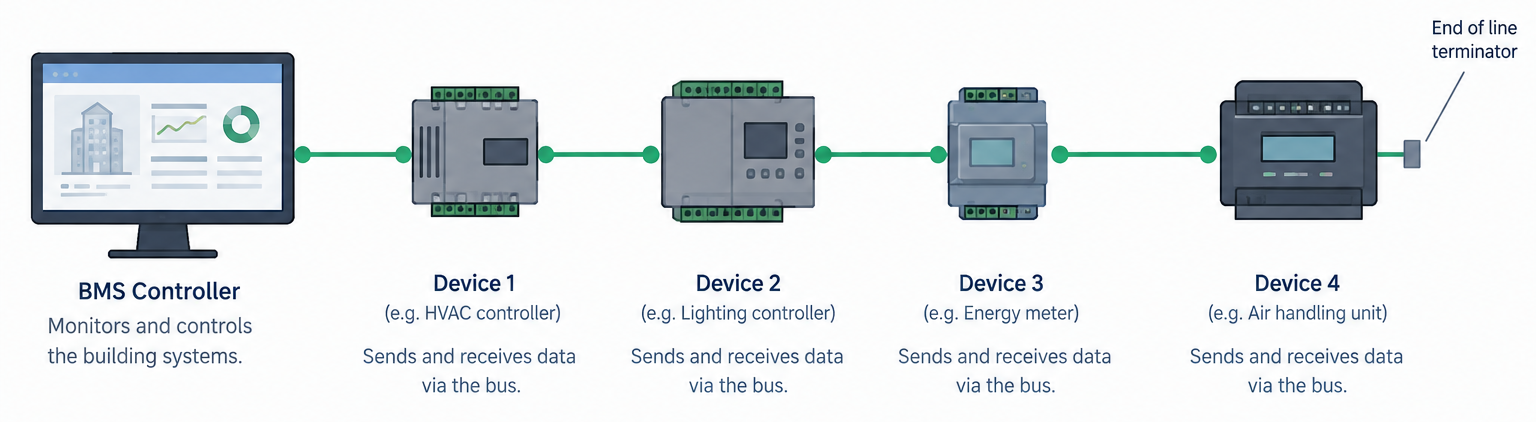
In a typical BMS daisy-chain architecture, a battery-monitoring IC or module communicates with the next module in sequence. This provides a serial communication path across the battery pack, often between modules operating at different electrical potentials.
- Reduced wiring compared with individual point-to-point connections.
- A scalable approach for higher cell counts.
- Simplified routing across distributed battery-monitoring modules.
- Structured collection of cell-voltage and temperature data across the pack.
Every additional node, connector, PCB trace and cable section becomes part of the complete communication path. A weakness in one link can affect the performance of the wider chain. The engineering question is not merely whether data can be sent, but whether the full chain can transfer accurate, stable information under real operating conditions.
High Voltage Changes the Communication Environment
BMS modules may sit at significantly different common-mode potentials. The battery pack may also be exposed to switching noise from inverters, DC/DC converters, contactors and other high-power electronics. This makes the communication environment fundamentally different from a short, low-voltage local data link.
- Galvanic isolation between sections of the communication chain.
- Insulation performance under high-voltage conditions.
- Common-mode noise coupling into communication lines.
- Signal attenuation, distortion or reflection across multiple links.
- PCB layout, connector design, cable routing and operating-temperature range.
Signal Integrity Across Multiple Nodes
In a daisy-chain architecture, communication quality is influenced by the accumulated behaviour of the chain. The electrical characteristics of every link can affect the overall result. Impedance discontinuities, excessive parasitic capacitance, poor routing or unsuitable magnetic components may increase signal distortion, reflections or electromagnetic sensitivity.
This is particularly important in isolated serial communication architectures, including systems based on isoSPI or similar approaches. Engineers need to consider whether the transmission path is matched to the communication architecture, whether the isolation solution preserves the required signal bandwidth and waveform quality, and whether the complete chain has been assessed together.
Isolation voltage alone is not enough. The full system requirement must guide the component selection.
Transformer Based Isolation in BMS Communication
Transformer-based isolation can support galvanic isolation while enabling signal transmission between modules at different electrical potentials. For the intended application, the transformer must balance insulation performance with coupling characteristics, leakage inductance, DCR, temperature stability and PCB-space constraints.
The aim is not simply to place an isolation barrier between two nodes. It is to create a communication path that can remain stable, robust and manufacturable within the wider BMS system.
An Engineering Example for BMS Daisy Chain Communication
VIEEC ST06A01A0 is a single-channel BMS isolation transformer designed for BMS daisy-chain and isoSPI communication applications. Its documented characteristics include:
| Parameter | ST06A01A0 |
|---|---|
| Channels | Single channel with integrated choke |
| Turns ratio | 1:1 |
| Working voltage | 1,000 VDC |
| Isolation test | 4,300 VDC for 60 seconds |
| Operating temperature | -40°C to +125°C |
| Qualification | AEC-Q200 compliant |
| Minimum inductance | 150 µH |
| Maximum leakage inductance | 0.5 µH |
| DCR | 450 mΩ primary / 850 mΩ secondary |
| Package | Approx. 9.35 × 7.6 × 5.65 mm |
These values describe documented product characteristics. Final suitability must still be verified against the customer’s BMS architecture, monitoring IC, PCB layout, insulation requirements and validation conditions.
The Right Starting Question
For BMS daisy-chain communication, the right starting point is not which isolation component has the highest voltage rating. It is whether the communication path can remain reliable across the complete battery pack, under the voltage, EMI, temperature and validation conditions of the actual system.
At VIEEC Ireland, we start with the application architecture and the customer’s system requirements. From there, we work with our engineering teams to assess the appropriate magnetic solution for the communication link.