Same Common Mode Noise Different Engineering Priorities
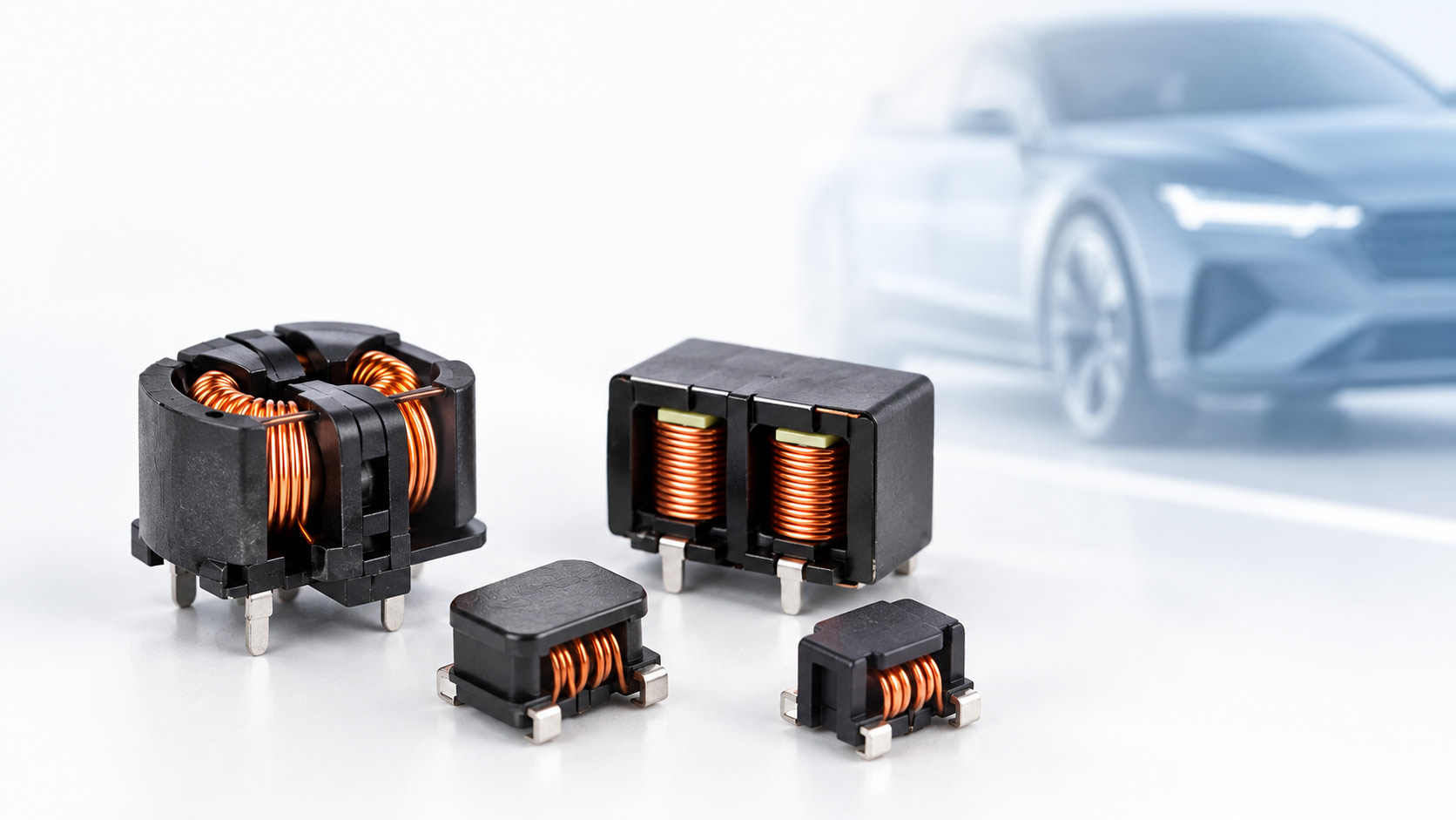
Common-mode chokes are used across automotive electronics to help control electromagnetic interference. They may appear on CAN networks, automotive Ethernet links, battery-management systems, DC/DC converters and vehicle power lines. Although their shared purpose is to attenuate common-mode noise, a choke protecting a communication link and one carrying vehicle power must be selected against very different engineering priorities.
The electrical principle
In a balanced communication interface, the wanted differential signal travels as equal and opposite currents on the two conductors. Common-mode noise, by contrast, appears in the same direction on both conductors relative to the system reference. A common-mode choke is designed to present impedance to that unwanted disturbance while having minimal impact on the wanted differential transmission.
That principle applies to both signal and power applications. The key difference is what the line must continue to carry after the noise has been attenuated.
Signal line CMCs
Suppress the noise. Preserve the signal.
For CAN-BUS, CAN-FD, 100BASE-T1 and 1000BASE-T1, the CMC is part of a communication path. It must help control common-mode emissions and susceptibility without degrading signal integrity. A high impedance value at one frequency does not, by itself, establish suitability for a given communication interface.
The selection must be assessed against the relevant frequency range, transmission requirements and validation conditions. For automotive signal lines, engineers may need to consider:
- the communication interface and data-rate requirements;
- the frequency range and source of the common-mode noise;
- common-mode attenuation across the relevant band;
- differential-mode insertion loss and transmission characteristics;
- line balance, PCB layout, package dimensions and operating temperature; and
- customer-specific PHY, EMC and system-validation conditions.
The practical question is not simply whether a component filters strongly. It is whether it can attenuate the unwanted common-mode noise without compromising the intended differential communication signal.
| Application | VIEEC signal-line CMC families |
| CAN-BUS | AC-3225B-U0 / AC-4532A-U0 |
| CAN-FD | AC-3225B-U5 |
| 100BASE-T1 | AC-3225B-U4 / AC-4532A-U4 |
| 1000BASE-T1 | AC-3225B-U3 / AC-4532A-U3 |
The final part-number selection should always be confirmed against the applicable system requirements, transceiver configuration, PCB layout and project test conditions.
Power line CMCs
Suppress the noise. Carry the required current efficiently.
On an automotive power line, common-mode noise suppression remains the objective. However, the CMC must also carry the required current with acceptable voltage drop, power loss and temperature rise. Selection therefore extends beyond impedance across the relevant noise-frequency range.
Power-line CMC selection needs to consider rated current, rated voltage, DC resistance, expected power loss, thermal behaviour, installation conditions, mechanical dimensions and long-term reliability under the project’s actual loading conditions.
DC resistance is particularly important in higher-current applications. Lower DCR helps reduce resistive loss and voltage drop, while thermal performance must be assessed under the actual current, ambient temperature and installation conditions.
The AL-7060A automotive power-line CMC series illustrates the wider range of considerations involved. Across the series, available options cover:
| Parameter | Available series range |
| Rated current | 0.9-15 A |
| Rated voltage | Up to 125 V |
| Typical common-mode impedance at 100 MHz | 70-3,000 ohms |
| Maximum DCR | 5-75 mOhm |
These are series ranges only. The actual parameter combination depends on the selected part number and the requirements of the application.
One component family Two different selection paths
| Signal line | Power line |
| Communication interface | Required current and voltage |
| Noise-frequency range | Noise-frequency range |
| Signal integrity and transmission characteristics | DCR, power loss and thermal performance |
| Common-mode attenuation | Common-mode attenuation |
| CMC selection | CMC selection |
At VIEEC Ireland, we do not start a CMC discussion by asking which part has the highest impedance. We start by understanding the system: what noise needs to be controlled, and what the line must continue to carry. The application should define the magnetic component, not a single number on a datasheet.